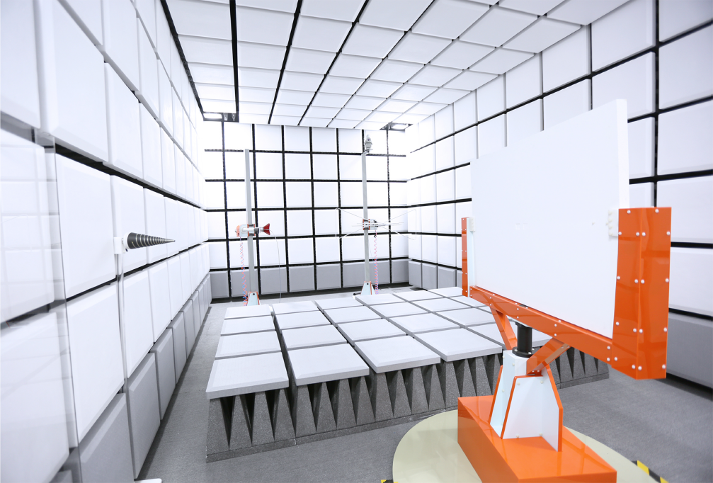
The 3m Full Anechoic Chamber is designed to conduct comprehensive compliance measurements of radiated emissions and immunity at a 3-meter testing distance. This versatile EMC test facility is utilized for both commercial and telecommunications testing. The chamber features a robust construction, including a 2mm galvanized pan-type panel system, parallel-closing RF shielded doors, and polystyrene hybrid absorbers on the walls, floor, and ceiling. These elements work together to create a high-performance, controlled electromagnetic environment that meets international standards for immunity and emission testing.
Product Description
The main purpose of a 3m full anechoic chamber is to perform full compliance measurements of radiated emission and immunity at 3m test distance. The 3m full anechoic chamber is a multi-functional EMC test facility for commercial and telecom testing. The combination of the pan-type 2mm galvanized panel system, parallel closing RF shielded doors and polystyrene hybrid absorbers on the walls, floor and ceiling creates a high performance controlled electromagnetic environment that complies with international immunity and emission test standards.
Features of a 3m full anechoic chamber:
Full compliance emission test site for frequency range of 30MHz to 18GHz as per CISPR 16-1-4 (2010) +annex A1 (2012) (free space testing)
Full compliance immunity test site for frequency range of 80MHz to 6GHz as per IEC/EN 61000-4-3
Shielding effectiveness according to EN 50147-1 (>80dB at 10kHz)
Acceptance standards for a 3m full anechoic chamber:
CISPR 16-1-4
IEC/EN 61000-4-3
EN 50147-1
ANSI C63.4
Product standards for a 3m full anechoic chamber:
CISPR 32
CISPR 35
CISPR 11
CISPR 14
CISPR 15
Typical performance of a 3m full anechoic chamber:
FSNSA: +/-3.5dB at 3m test distance
sVSWR: ≤ 5.5dB at 3m test distance
FU: 75% of 16 points ≤ 6dB at 3m test distance & 1.5*1.5m test window (0.8m above floor level)
Typical specifications for a 3m full anechoic chamber:
| External dimensions | 8.8m*5.8m*4.8m(L*W*H) |
| Dimensions | 8.2m*5.2m*4.2m(L*W*H) |
| Control room dimensions | 4.0m*4.0m*3.0m(L*W*H) |
| Amplifier room dimensions | 4.0m*2.1m*3.0m(L*W*H) |
| Construction | 2mm galvanized shielding panels with a free standing structural steel support |
| Absorbers | Hybrid solution of ferrite tiles and polystyrene hybrid absorber on walls, floor and ceiling |
| Ventilation | 300mm*300mm/18GHz |
| Shielded door | RF shielded swing door 1.2m*2.1m (W*H) |
| Ground interface board | 400mm*400mm/18GHz, including RF connectors |
| EUT power line | Filtered 220V 32A 50Hz/60Hz; 380V 63A 50Hz/60Hz |
| Lighting | Interference-free LED automatic lifting and lighting system |
| Frequency range | 30MHz to 18GHz for radiated emission and 80MHz to 6GHz for radiated immunity |
| Quiet zone size | Diameter 1.5m, height 1.5m |
| Floor | Ferrite tiles and hybrid absorbers incl. a walk way solution. |
| Positioning system | Optical fiber control turntable, turntable diameter 2m;Optical fiber control antenna tower, 1-3m lifting. |